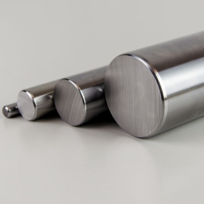
Shafts and supports
/ 5 Reviews :
You can always check the current price and availability of rollers after logging in to our online store.
Worth knowing:
- Shafts, made of Ck55/Cf53 materials, surface hardened to 59±6 HRC ensure maximum linear bearing life.
- Precise roller grinding allows for obtaining a surface roughness of 0.2 m.
- Shafts made of Ck55/Cf53/ .
- The soft core ensures high strength parameters and allows for subsequent processing.
- It is possible to perform turning and milling processing in our company's machining center.
- Implementation of machining based on the manufacturing drawings provided by the client or provided patterns.
- Metric sizes with diameters from 3 mm to up to 100 mm and inch sizes with a diameter from 1/4" to 3' available from stock.
- Shafts cut to size within a tolerance of ±0.2 mm, higher accuracy on request.
- For environments exposed to corrosion, we offer rollers made of martensitic stainless steel: X46Cr13(1.4034)< /span> — surface hardened to 52±2 HRC and X90CrMoV18 (1.4112) — surface hardened to >55 HRC, both types of steel available from stock.
- Fundamental differences between both steel grades X46Cr13 (1.4034) and X90CrMoV18 (1.4112) :
|
Chemical composition [%] |
|||||||||
|
Steel grade |
C |
S |
P |
Si |
Mn |
Cr |
Mo |
V |
|
|
X46Cr13 ( 1.4034 / AISI420C ) |
0.45 |
0.003 |
0.03 |
0.4 |
0.5 |
13 |
- |
- |
|
|
X90CrMoV18 (1.4112 / AISI440B ) |
0.9 |
0.005 |
0.03 |
0.5 |
0.5 |
17 |
1 |
0.1 |
|
- higher steel corrosion resistance X90CrMoV18, resistance to fresh water and steam and resistance to operating temperatures < 400℃.
- steel X90CrMoV18 undergoes heat treatment and obtains hardness and high abrasion resistance unusual for corrosion-resistant steels, and is also highly polished
- steel X46Cr13 is well machinable, hardenable and polish
- X46Cr13 steel has sufficient corrosion resistance to environments containing certain organic acids, substances without chlorides, weak alkalis.
- Generally, X46Cr13 steel and X90CrMoV18 steel are stainless steels, they are not suitable for use in acidic environments; acid-resistant steels are required there
 |
 |
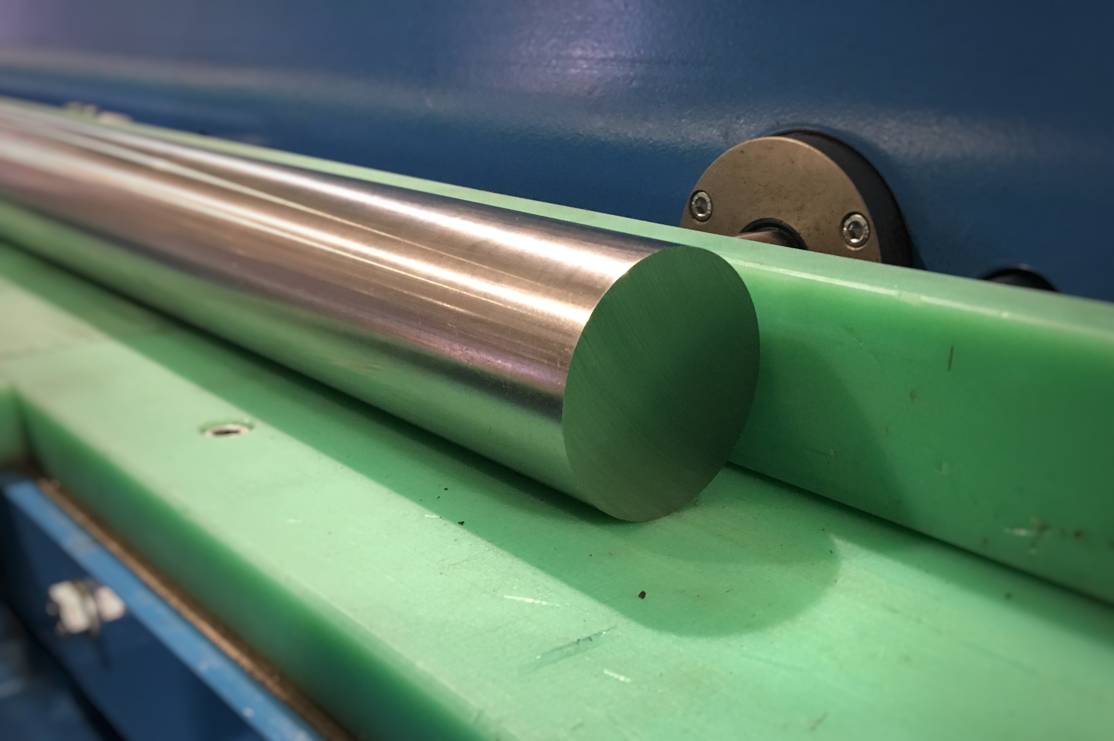
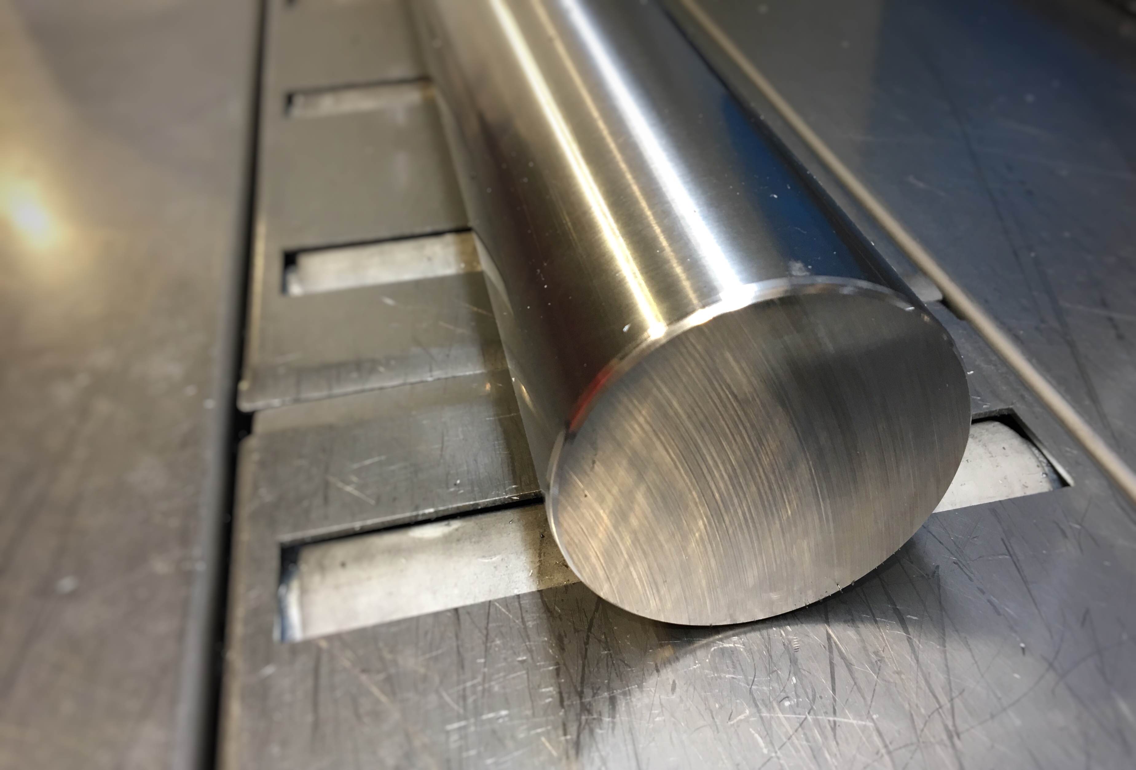
| Before cutting and chamfering the 60mm shaft. | After cutting and chamfering the 60mm shaft. |
| Size |
Diameter d |
Weight [kg/m] |
Depth |
Location and size |
|
| W 03h6 | 3 | 0.06 | 0.4÷0.8 | 0 | -8 |
| W 04h6 | 4 | 0.10 | 0.4÷0.8 | 0 | -8 |
| W 05h6 | 5 | 0.15 | 0.4÷0.8 | 0 | -8 |
| W 06h6 | 6 | 0.22 | 0.4÷0.8 | 0 | -8 |
| 1/4" | 6.35 (1/4") | 0.25 | 0.5÷0.8 | -13 | -25 |
| W 07h6 | 7 | 0.30 | 0.5÷0.8 | 0 | -9 |
| W 08h6 | 8 | 0.39 | 0.4÷0.8 | 0 | -9 |
| W 3/8" | 9.53 (3/8") | 0.56 | 0.6÷0.9 | -13 | -25 |
| W 10h6 | 10 | 0.61 | 0.4÷0.8 | 0 | -9 |
| W 12h6 | 12 | 0.88 | 0.6÷1.2 | 0 | -11 |
| 1/2" | 12.70 (1/2") | 0.99 | 0.8÷1.2 | -13 | -25 |
| W 13h6 | 13 | 1.04 | 0.8÷1.2 | 0 | -11 |
| W 14h6 | 14 | 1.20 | 0.6÷1.2 | 0 | -11 |
| W 15h6 | 15 | 1.38 | 0.6÷1.2 | 0 | -11 |
| W 5/8" | 15,875 (5/8) | 1.54 | 1.0÷1.4 | -13 | -25 |
| W 16h6 | 16 | 1.57 | 0.6÷1.2 | 0 | -11 |
| W 17h6 | 17 | 1.77 | 0.6÷1.2 | 0 | -11 |
| W 18h6 | 18 | 1.98 | 1,1÷1,5 | 0 | -11 |
| >3/4" | 19.05 (3/4") | 2.22 | 1,2÷1,5 | -13 | -25 |
| W 20h6 | 20 | 2.45 | 0.9÷1.8 | 0 | -13 |
| W 22h6 | 22 | 2.97 | 1,2÷1,5 | 0 | -13 |
| W 24h6 | 24 | 3.53 | 1,2÷1,5 | 0 | -13 |
| W 25h6 | 25 | 3.83 | 0.9÷1.8 | 0 | -13 |
| W 1" | 25.40 (1") | 3.95 | 1.5÷1.7 | -13 | -25 |
| W 28h6 | 28 | 4.80 | 0.9÷1.8 | 0 | -13 |
| W 1 1/8' | 28,575 (1 1/8") | 5.00 | 1.5÷1.8 | -13 | -25 |
| W 30h6 | 30 | 5.51 | 1.5÷1.9 | 0 | -13 |
| W 1 1/4" | 31.75 (1 1/4") | 6.18 | 1.5÷1.9 | -13 | -25 |
| W 32h6 | 32 | 6.27 | 1.5÷1.9 | 0 | -16 |
| W 1 3/8' | 34,925 (1 3/8") | 7.47 | 1.5÷1.9 | -13 | -25 |
| W 35h6 | 35 | 7.50 | 1.5÷1.9 | 0 | -16 |
| W 1 1/2" | 38.1 (1 1/2") | 8.89 | 1.6÷2.0 | -15 | -28 |
| W 40h6 | 40 | 9.80 | 1.5÷2.8 | 0 | -16 |
| W 45h6 | 45 | 12.41 | 1.6÷2.0 | 0 | -16 |
| W 50h6 | 50 | 15.32 | 1.5÷2.8 | 0 | -16 |
| W 2 | 50.8 (2") | 15.81 | 2,2÷2,6 | -15 | -33 |
| W 2 1/4" | 57.15 (2 1/4") | 20.01 | 2,2÷2,6 | -18 | -38 |
| W 60h6 | 60 | 22.05 | 2,2÷3,8 | 0 | -19 |
| W 2 1/2" | 63.5 (2 1/2") | 24.70 | 2,2÷2,6 | -18 | -38 |
| W 70h6 | 70 | 30.02 | 2,2÷2,6 | 0 | -19 |
| W 3 | 76.2 (3") | 35.57 | 2,2÷2,6 | -20 | -43 |
| W 80h6 | 80 | 39.21 | 2,2÷3,8 | 0 | -19 |
| W 100h6 | 100 | 61.26 | 2,2÷3,2 | 0 | -22 |
| Size | Diameter d [mm] | Internal average | Weight [kg/m] | Hardening depth [mm] | Position and size of the tolerance field [µm] | |
| WH 12h6 | 12 | 4 | 0.78 | 0.6÷1.2 | 0 | -11 |
| WH 16h7 | 16 | 7 | 1.27 | 0.6÷1.2 | 0 | -18 |
| WH 20h7 | 20 | 14 | 1.25 | 0.9÷1.8 | 0 | -21 |
| WH 25h7 | 25 | 15.4 | 2.38 | 0.9÷1.8 | 0 | -21 |
| WH 30h7 | 30 | 18.3 | 3.46 | 0.9÷1.8 | 0 | -21 |
| WH 40h7 | 40 | 26 | 5 | 1.5÷2.8 | 0 | -25 |
SK roller end support
End brackets made of anodized aluminum.
TSN supports and supports with TSNW roller.
Longitudinal supports made of anodized aluminum, supplied without or with an mounted precision shaftsteel.
FRC pneumatic clamp.
The clamping is done via a wedge gear. Clamps made of structural steel ensure high axial and radial stiffness.
FRCCMANLT manual roller clamp.
Simple and reliable manual clamping element. It allows for the modern clamping of the lock jaws on a profile rail or shaft. Self-adjusting jaws ensure symmetrical force distribution on the linear guide.


